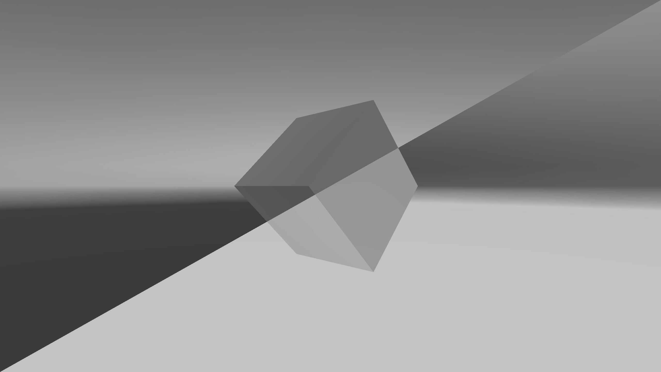
Figure 9.1: Negative-Positive Inversion with ImageEffect
Figure 9.1: Negative-Positive Inversion with ImageEffect
A simple explanation of how to implement ImageEffect, a technology that applies effects to the output video using a shader (GPU), in Unity. The technology is also known as PostEffect.
ImageEffect is used for glow effects that express light, anti-aliasing that reduces jaggies, depth of field DOF, and much more. The simplest example would be a color change or modification that also deals with the sample presented here.
This chapter is written on the assumption that you have some prerequisite knowledge about the basic knowledge and usage of Unlit shader and Surface shader, but since it is the shader with the simplest configuration, even if you do not have the prerequisite knowledge, I think you can read on and use it.
The sample in this chapter is "Simple Image Effect" from
https://github.com/IndieVisualLab/UnityGraphicsProgramming2
.
The way ImageEffect achieves various effects is, in a nutshell, image processing, that is, by manipulating the screen pixel by pixel, various effects are achieved.
Speaking of processing pixels by shaders, it is a fragment shader. In essence, implementing an ImageEffect is equivalent to implementing a fragment shader.
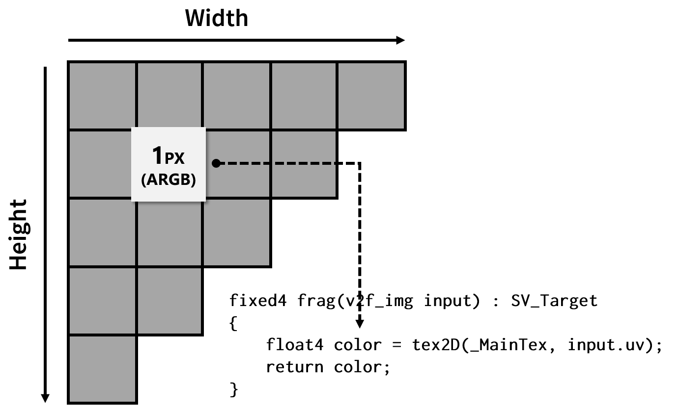
Figure 9.2: ImageEffect implementation implements fragment shader
In Unity, the processing order of ImageEffect is roughly as follows.
We have prepared the simplest sample scene. Open the sample "ImageEffectBase" scene to see it. The associated script and other resources have the same name.
A similar sample has a resource with the same name as the ImageEffect scene, but be aware that it will be discussed later.
When you open the sample, the image projected by the camera in the scene will be negatively and positively inverted by ImageEffect. This is equivalent to the shader for ImageEffect that Unity generates by default, but the actual source code is slightly different.
Make sure the "ImageEffectBase" script is attached to the "Main Camera" in the sample scene. In addition, "ImageEffectBase" references a material with the same name, and that material has a shader with the same name.
First of all, I will explain the process from calling the Shader of ImageEffect from the script.
When you want to make changes to the video that Unity outputs, you almost always need to implement the OnRenderImage method. OnRenderImage is a method defined in Unity's standard workflow, like Start and Update.
ImageEffectBase.cs
[ExecuteInEditMode]
[RequireComponent(typeof(Camera))]
public class ImageEffectBase : MonoBehaviour
{
…
protected virtual void OnRenderImage
    (RenderTexture source, RenderTexture destination)
{
    Graphics.Blit(source, destination, this.material);
}
OnRenderImage is only called when it is added to a GameObject that has a Camera component. Therefore, the ImageEffect class [RequireComponent(typeof(Camera))]defines.
The ExcludeInEditModeattributes are also defined because the result of applying ImageEffect should be visible before running Scene . Disable the ImageEffect script when you want to switch between multiple ImageEffects and check when they are disabled.
OnRenderImage is given an input in the first argument (source) and an output destination in the second (destination). Both are of type RenderTexture, but unless otherwise specified, source is given the drawing result of the camera and destination is given null.
ImageEffect modifies the picture entered in source and writes it to destination, but when destination is null, the modified picture is output to the framebuffer, the area visible to the display.
Also, when RenderTexture is set to the output destination of the Camera, the source is equivalent to that RenderTexture.
Graphics.BlitThe method is the process of drawing the input RenderTexture to the output RenderTexture using the specified material and shader. The inputs and outputs here are the source and destination of the OnRenderImage. Also, the material will be the one with the shader set for ImageEffect.
As a general rule, the OnRenderImage method must always pass some image data to the destination argument. Therefore, in most cases Graphics.Blit is called within OnRenderImage.
It Graphics.Blitmay also be used as an application, for example, when creating a texture for use in another effect, or when duplicating a texture . Alternatively, you may use another method to pass the data to the destination, but I'll omit those application examples here for the sake of getting started.
The following items are a little different from the process of applying ImageEffect, so if you are reading for the first time, it is recommended that you skip to the shader description.
I don't think it is necessary to implement or explain this item when explaining ImageEffect, but I decided to explain it so that it would not be an obstacle when reading materials with more practical implementations. Equivalent functionality is implemented in the ImageEffect documentation provided by Unity.
ImageEffect is a process that is calculated for each pixel. Therefore, in an execution environment without an advanced GPU, ImageEffect may not be welcomed due to the large number of operations. Therefore, it is helpful to verify at the start whether ImageEffect is available in the execution environment and disable it if it is not available.
ImageEffectBase.cs
protected virtual void Start()
{
    if (!SystemInfo.supportsImageEffects
     || !this.material
     || !this.material.shader.isSupported)
    {
        base.enabled = false;
    }
}
Verification SystemInfo.supportsImageEffectscan be easily achieved by providing Unity .
This implementation will be useful in most cases, but you may need a different implementation, for example when using the fallback feature implemented on the shader side. Please refer to it to the last.
The only this.materialthing you need to be aware of is when to validate the reference. The example validates with the Start method, but when this is Awake or OnEnable this.material, Unity will show null (and base.enabled = falsewill invalidate the script) , even if a reference is given to , for example . Details are omitted, but ExcludeInEditModeit depends on the specifications (it is hard to say that it is harmful).
Next, I will explain about the ImageEffect shader. The most basic sample presented here implements the effect of just flipping the output colors, similar to what Unity creates as standard.
ImageEffectBase.shader
Shader "ImageEffectBase"
{
    Properties
    {
        _MainTex("Texture", 2D) = "white" {}
    }
    SubShader
    {
        Cull Off ZWrite Off ZTest Always

        Pass
        {
            CGPROGRAM

            #include "UnityCG.cginc"
            #pragma vertex vert_img
            #pragma fragment frag

            sampler2D _MainTex;

            fixed4 frag(v2f_img input) : SV_Target
            {
                float4 color = tex2D(_MainTex, input.uv);
                color.rgb = 1 - color.rgb;

                return color;
            }

            ENDCG
        }
    }
}
As a rough process flow, _MainTexthe image drawn by the camera is input to, and the fragment shader determines the final color to be displayed on the pixel.
Here _MainTextexture information given to OnRenderImagethe source, Graphics.Blitthe sourceis equal to.
_MainTexTooth Graphics.BlitPlease note that has been reserved by the Unity for input. If you change to a different other name, Graphics.Blitthe sourceis not entered correctly shader.
The ImageEffect that Unity generates by default is a bit long and complex (excerpt): ImageEffect is also a shader, so you get the final output through a standard rendering pipeline. Therefore, a vertex shader that does not seem to affect the effect that ImageEffect achieves must also be defined in the ImageEffect shader.
NewImageEffectShader.shader
SubShader
{
    Cull Off ZWrite Off ZTest Always

    Pass
    {
        CGPROGRAM
        #pragma vertex vert
        #pragma fragment frag

        #include "UnityCG.cginc"

        struct appdata
        {
            float4 vertex : POSITION;
            float2 uv : TEXCOORD0;
        };

        struct v2f
        {
            float2 uv : TEXCOORD0;
            float4 vertex : SV_POSITION;
        };

        v2f vert (appdata v)
        {
            v2f o;
            o.vertex = UnityObjectToClipPos(v.vertex);
            o.uv = v.uv;
            return o;
        }

        sampler2D _MainTex;

        fixed4 frag (v2f i) : SV_Target
        {
            fixed4 col = tex2D(_MainTex, i.uv);
            col.rgb = 1 - col.rgb;
            return col;
        }
        ENDCG
    }
}
The vertex shader in ImageEffect simply faces the camera and passes a rectangular mesh that fills the entire surface and its UV coordinates to the fragment shader. There are some benefits that can be achieved by modifying this vertex shader, but most ImageEffects do not.
That's why Unity provides a standard vertex shader and a structure to define its inputs. They are defined in "UnityCG.cginc". Here, in the source code of the shader is not a prepared standard, defined in the UnityCg.cginc vertex vert_imgYa appdata, v2f_imgby making use of, and to simplify the entire source code.
At first glance, standard values seem to be fine for culling, writing and referencing the Z-buffer. However, Unity Cull Off ZWrite Off ZTest Alwaysrecommends defining to prevent inadvertent writing to the Z-buffer .
Let's practice ImageEffect easily. The sample simply flips the full screen negatively and positively, but try applying negative and positive flipping "only to the diagonal half" of the entire image, as shown in the figure at the beginning of this chapter.
input.uvIs given coordinates that indicate one pixel of the entire image, so take advantage of this. Each pixel in the entire image is represented by the x * y coordinates normalized by 0 to 1.
An example code that works is included in the sample "Prtactice" folder and will be explained later, but if you are new to it, try implementing it yourself first. I recommend that.
It's very easy to change the color in the upper and lower halves. This is a good way to see the origin of the ImageEffect's coordinates. For example, the following two lines of code invert colors when the x and y coordinates are less than half, respectively.
Practice/ImageEffectShader_01.shader
color.rgb = input.uv.x < 0.5 ? 1 - color.rgb : color.rgb;
color.rgb = input.uv.y < 0.5 ? 1 - color.rgb : color.rgb;
Did you confirm from the color change that the origin of the coordinates given to ImageEffect is the lower left?
I mentioned earlier that the top, bottom, left, and right halves are easy, but in reality, the diagonal halves are also easy. You can apply the effect (invert the color) diagonally in half with the following source code.
Practice/ImageEffectShader_02.shader
color.rgb = input.uv.y < input.uv.x ? 1 - color.rgb : color.rgb;
That was introduced as UnityCg.cginc The vertex vert_imgkilling appdataof such useful functions and structures have been defined, convenient value in implementing the ImageEffect In addition to these have been defined.
_ScreenParamsIs float4the type of value, x, yto the pixel width and height of the image to be output, respectively, w, zthe 1 + 1 / x, 1 + 1 / ywe are given.
For example, when you run the rendering of 640x480 size, x = 640, y = 480, z = 1 + 1 / 640, z = 1 + 1 / 480and will be. As a matter of fact, wand zit would not have to use so much.
On the other hand x, ythe value of is often used to calculate, for example, how many pixels on an image it corresponds to, or to calculate the aspect ratio. These are important for creating elaborate effects, but it would be helpful if Unity provided them without giving any values from the script. If you put it in the corner of your head, it may help you to read other shaders.
One of the similar <sampler2Dの変数名>_TexelSizedefinition values is. Here it _MainTex_TexelSizewill be.
_ScreenParamsWhen the same float4, but the type of values, x = 1 / width, y = 1 / height, z = width, y = heightand, different value given to each element. Another sampler2Dfeature is that the values differ depending on the corresponding type. _MainTexRegardless, ~_TexlSizeif you define a corresponding , Unity will give you a value.
_ScreenParamsThere are many ImageEffects that _MainTex_TexelSizeuse, but I think it 's easier to use.
For example, it is often the case in image processing that you want to refer to the color (value) of the next pixel, but you can refer to the value of the next pixel with the following code.
Practice/ImageEffectShader_03.shader
sampler2D _MainTex;
float4    _MainTex_TexelSize;

fixed4 frag(v2f_img input) : SV_Target
{
    float4 color = tex2D(_MainTex, input.uv);

    color += tex2D(_MainTex, input.uv + float2(_MainTex_TexelSize.x, 0));
    color += tex2D(_MainTex, input.uv - float2(_MainTex_TexelSize.x, 0));
    color += tex2D(_MainTex, input.uv + float2(0, _MainTex_TexelSize.y));
    color += tex2D(_MainTex, input.uv - float2(0, _MainTex_TexelSize.y));

    color = color / 5;

    return color;
}
This code references the four surrounding pixels and returns the average value. In image processing, it is literally called a smoothing filter. In addition, a higher quality noise reduction filter may be implemented by referring to the surrounding pixels in the same way, and it is also used in edge / contour detection filters, for example.
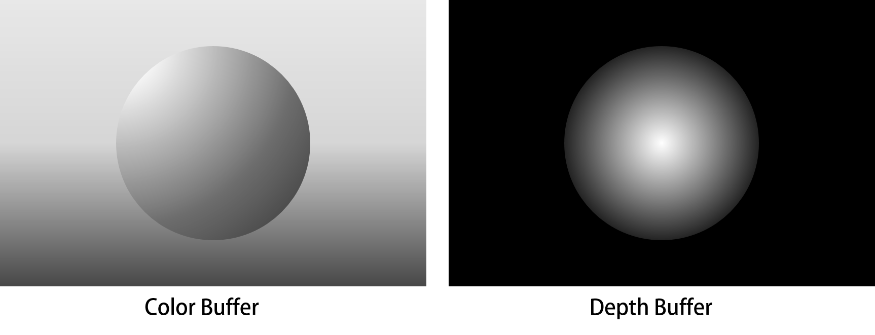
Figure 9.3: Image of G-Buffer
When implementing a material (shader) to apply to a model, you will often refer to the model's depth and normal information. ImageEffect, which manipulates two-dimensional image information, does not seem to be able to acquire depth and normal information, but there is a method to acquire the depth and normal information of an object projected on a certain pixel on the image. I have.
To explain the technical details, it is necessary to explain the rendering pipeline, which will be a little long, so let me omit it. Briefly, depth information and normal information corresponding to a pixel on the image to be drawn can be buffered. Those buffers are called G-Buffers. Some G-Buffers store colors and depths. (By the way, the original paper shows that the reading of G-Buffer is "game buffer".)
When drawing an object, the depth and normal information is also written in the buffer, and it is referenced by ImageEffect, which is executed at the end of drawing. This technique plays an important role in Deffered rendering, but it can also be used in Forward rendering.
These discussions use a sample "ImageEffect" scene and a resource with the same name.
A little setting is required to refer to the depth and normal information in ImageEffect. Since the basic functions are common, here we will set it in ImageEffect.cs, which inherits ImageEffectBase.cs.
ImageEffect.cs
public class ImageEffect : ImageEffectBase
{
    protected new Camera camera;
    public DepthTextureMode depthTextureMode;

    protected override void Start()
    {
        base.Start();

        this.camera = base.GetComponent<Camera>();
        this.camera.depthTextureMode = this.depthTextureMode;
    }

    protected virtual void OnValidate()
    {
        if (this.camera != null)
        {
            this.camera.depthTextureMode = this.depthTextureMode;
        }
    }
}
To get the depth and normal information, DepthTextureModeyou need to set the camera . This is a setting to control how information such as depth and normal is written. The initial value is None.
Unfortunately, it DepthTextureMode's a parameter that doesn't appear in the camera's Inspector, so you'll need to optionally get a camera reference from the script and set it.
OnValidate For those who haven't used the method very often, it is the method that is called when the parameter is updated on the Inspector.
Use the code presented here DepthTextureModeto change the value of inspector. There are some values, but DepthNormalsnote that we use here .
DepthIf is set, it will be the setting to acquire only the depth information. However Depththeft DepthNormalsdoor, the slightly different procedure to obtain the depth information from the shader. Also MotionVectorsby setting the, How can a lot of fun can get the information of the motion corresponding to each pixel, a little because the longer and all commentary, please let omitted in this place.
DepthTextureModeHere's how to get depth and normal information from the shader when set to camera :
_CameraDepthNormalsTextureIs _MainTexgiven depth and normal information, just as the image to draw is given sampler2D. Therefore input.uv, you can use to get the depth and normal information for a pixel with an image to draw.
ImageEffect.shader
sampler2D _MainTex;
sampler2D _CameraDepthNormalsTexture;

fixed4 frag(v2f_img input) : SV_Target
{
    float4 color = tex2D(_MainTex, input.uv);
    float3 normal;
    float  depth;

    DecodeDepthNormal
    (tex2D(_CameraDepthNormalsTexture, input.uv), depth, normal);

    depth = Linear01Depth(depth);
    return fixed4(depth, depth, depth, 1);

    return fixed4(normal.xyz, 1);
}
_CameraDepthNormalsTextureThe values that can be obtained from are the sum of the depth and normal values, so we need to decompose them into their respective values. The function for decomposing is the one provided by Unity. DecodeDepthNormalGive the function a variable to assign the value you want to decompose and the result.

Figure 9.4: Depth visualization with ImageEffect
I will explain the depth information first. Depth information is actually handled differently depending on the platform. Unity provides some mechanisms to absorb the difference Linear01Depth, but I think it's better to use a function when implementing ImageEffect . Linear01DepthIs a function to normalize the obtained depth value from 0 to 1.
In the sample, the acquired depth value is given to R, G, and B to visualize the depth value. Clipping PlanesIt is recommended to move the camera in the scene or change the value from the Inspector to see how it changes.

Figure 9.5: ImageEffect Visualization of Normals
Visualization of normal information is not as complicated as depth information. The normal information is equivalent to that referenced by scripts and common shaders. X, YZ information indicating the direction of the surface projected on a pixel is given in a format normalized to 0 to 1.
If you just want to check if the normals are obtained correctly, you can output the values of X, Y, Z as R, G, B as they are. In other words, the face facing to the right has a larger value of X = R and becomes more red, and the face facing upward has a value of Y = G and becomes greener.
The main references in this chapter are: Both are official Unity.